Procedure
S-Flex Coupling Choice Method
The selection procedure for determining the right S-Flex coupling involves working with the charts proven on the following pages. You’ll find three parts for being chosen, two flanges and one particular sleeve.
Data needed in advance of a coupling is often chosen:
HP and RPM of Driver or working torque
Shaft size of Driver and Driven equipment and corresponding keyways
Application or products description
Environmental disorders (i.e. extreme temperature, corrosive ailments, space limitations)
Techniques In Selecting An S-Flex Coupling
Stage one: Decide the Nominal Torque in in-lb of the application by utilizing the following formula:
Nominal Torque = (HP x 63025)/RPM
Phase two: Using the Application Support Component Chart 1 decide on the service element which finest corresponds for your application.
Step 3: Determine the Design and style Torque of your application by multiplying the Nominal Torque calculated in Step one through the Application Service Element determined in Phase two.
Layout Torque = Nominal Torque x Application Support Component
Stage four: Working with the Sleeve Performance Information Chart two decide on the sleeve materials which finest corresponds for your application.
Step five: Utilizing the S-Flex Nominal Rated Torque Chart 3 find the acceptable sleeve material column for that sleeve chosen in Phase 4.
Phase six: Scan down this column for the 1st entry where the Torque Value inside the column is greater than or equal towards the Style and design Torque calculated in Stage three.
Refer to the greatest RPM worth on the coupling dimension to guarantee that the application requirements are met. When the optimum RPM value is much less compared to the application necessity, S-Flex couplings aren’t suggested to the application.
Note:
If Nominal Torque is significantly less than 1/4 on the coupling’s nominalrated torque, misalignment capacities are reduced by 1/2. When torque value is located, refer for the corresponding coupling dimension while in the first column of the S-Flex Nominal Rated Torque Data Chart 3 .
Step seven: Assess the application driver/driven shaft sizes to your optimum bore dimension offered over the coupling selected. If coupling max bore is not significant sufficient for that shaft diameter, pick the next largest coupling that should accommodate the driver/driven shaft 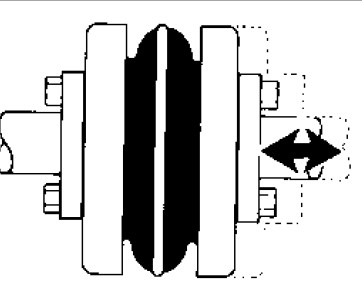 diameters.
Stage 8: Applying the Item Selection tables, locate the appropriate Keyway and Bore size demanded and find the number.