Product Description
SC Transmission FCL Flexible Shaft Couplings for Reducer and Motor
Product Description
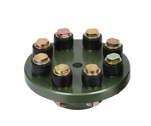
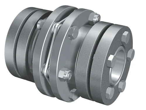
FCL Coupling/Shaft Coupling /Pin & Bush Coupling /FCL Flexible Coupling/NBK FCL Coupling is widely used for its compacts designing, easy installation, convenient maintenance, small and light weight.
As long as the relative displacement between shafts is kept within the specified tolerance, couplings will operate the best function and have a longer working life.
Thus it is greatly demanded in medium and minor power transmission systems driven by motors, such as speed reducers, hoists, compressors, conveyors, spinning and weaving machines and ball mills.
Product Parameters
| SIZE | D | D1 | d1 | L | C | n-M | kg | |||
| r/min | ||||||||||
| N.m | ||||||||||
| FCL90 | 4 | 4000 | 90 | 35.5 | 11 | 28 | 3 | 4-M8 | 1.7 | |
| FCL100 | 10 | 4000 | 100 | 40 | 11 | 35.5 | 3 | 4-M10 | 2.3 | |
| FCL112 | 16 | 4000 | 112 | 45 | 13 | 40 | 3 | 4-M10 | 2.8 | |
| FCL125 | 25 | 4000 | 125 | 65 | 50 | 13 | 45 | 3 | 4-M12 | 4 |
| FCL140 | 50 | 4000 | 140 | 71 | 63 | 13 | 50 | 3 | 6-M12 | 5.4 |
| FCL160 | 110 | 4000 | 160 | 80 | 15 | 56 | 3 | 8-M12 | 8 | |
| FCL180 | 157 | 3500 | 180 | 90 | 15 | 63 | 3 | 8-M12 | 10.5 | |
| FCL200 | 245 | 3200 | 200 | 100 | 21 | 71 | 4 | 8-M20 | 16.2 | |
| FCL224 | 392 | 2850 | 224 | 112 | 21 | 80 | 4 | 8-M20 | 21.3 | |
| FCL250 | 618 | 2550 | 250 | 125 | 25 | 90 | 4 | 8-M24 | 31.6 | |
| FCL280 | 980 | 2300 | 280 | 140 | 34 | 100 | 4 | 8-M24 | 44 | |
| FCL315 | 1568 | 2050 | 315 | 160 | 41 | 112 | 4 | 10-M24 | 57.7 | |
| FCL355 | 2450 | 1800 | 355 | 180 | 60 | 125 | 5 | 8-M30 | 89.5 | |
| FCL400 | 3920 | 1600 | 400 | 200 | 60 | 125 | 5 | 10-M30 | 113 | |
| FCL450 | 6174 | 1400 | 450 | 224 | 65 | 140 | 5 | 12-M30 | 145 | |
| FCL560 | 9800 | 1150 | 560 | 250 | 85 | 160 | 5 | 14-M30 | 229 | |
| FCL630 | 15680 | 1000 | 630 | 280 | 95 | 180 | 5 | 18-M30 | 296 | |
Company Profile
FAQ
Shipping
/* January 22, 2571 19:08:37 */!function(){function s(e,r){var a,o={};try{e&&e.split(“,”).forEach(function(e,t){e&&(a=e.match(/(.*?):(.*)$/))&&1
How does a flexible coupling contribute to the longevity of connected equipment?
A flexible coupling plays a crucial role in enhancing the longevity of connected equipment in various ways. It acts as a mechanical interface between two shafts, connecting them while accommodating misalignment, dampening vibrations, and transmitting torque. Here’s how a flexible coupling contributes to the longevity of connected equipment:
- Misalignment Compensation: One of the primary functions of a flexible coupling is to compensate for both angular and parallel misalignment between two shafts. Misalignment can occur due to various factors, including thermal expansion, assembly errors, or settling of foundation, which can exert excessive stress on the connected equipment. By allowing misalignment, the flexible coupling reduces the stress transmitted to the shafts and connected components, preventing premature wear and failure.
- Shock and Vibration Dampening: Flexible couplings are designed to absorb shocks and dampen vibrations that occur during operation. Vibrations and shocks can be detrimental to connected equipment, leading to fatigue, wear, and premature failure of components. The coupling acts as a buffer, reducing the impact of vibrations and protecting the equipment from potential damage.
- Reduced Stress Concentration: A rigid coupling can create stress concentration points on the shafts, leading to fatigue and cracking over time. Flexible couplings distribute the load more evenly along the shafts, reducing stress concentration and minimizing the risk of failure.
- Transmitting Torque Smoothly: Flexible couplings transmit torque from one shaft to another smoothly, without introducing sudden torque spikes or shocks. This even torque transfer prevents sudden loading on connected equipment, minimizing the risk of damage or accelerated wear on gears, bearings, and other components.
- Controlling Torsional Vibrations: In systems where torsional vibrations are a concern, certain types of flexible couplings are designed to address this issue. These couplings help control torsional vibrations, which can be damaging to the equipment and cause premature failure.
- Thermal Expansion Compensation: When the equipment operates at different temperatures, thermal expansion can lead to misalignment between the shafts. A flexible coupling can accommodate the thermal expansion, ensuring that the connected equipment remains aligned and preventing stress on the components.
- Isolation from External Forces: External forces like impact loads or shaft disturbances can affect the connected equipment. A flexible coupling isolates the equipment from these external forces, protecting it from potential damage.
By providing these essential functions, a flexible coupling helps extend the lifespan of connected equipment by reducing wear and tear, preventing premature failures, and ensuring smooth, reliable operation. The longevity of the connected equipment ultimately results in reduced maintenance costs and increased productivity.
What are the differences between single and double flexible coupling designs?
Single and double flexible couplings are two common designs used for power transmission in various mechanical systems. Here are the main differences between the two:
- Design: The primary difference lies in their configuration. A single flexible coupling consists of one flexible element connecting two shafts, while a double flexible coupling, also known as a two-piece flexible coupling, uses two flexible elements with an intermediate shaft in between. The double flexible coupling resembles two single couplings connected in series.
- Torsional Flexibility: Single flexible couplings typically provide greater torsional flexibility than double flexible couplings. The presence of an intermediate shaft in the double coupling design adds some rigidity and reduces the overall torsional flexibility of the system.
- Compensation of Misalignment: Both single and double flexible couplings can compensate for angular and parallel misalignment between shafts. However, due to its additional flexible element, the double flexible coupling may have slightly better misalignment compensation capabilities.
- Length and Space: Single flexible couplings are generally shorter in length compared to double flexible couplings. The double flexible coupling’s design requires additional space to accommodate the intermediate shaft, making it longer than the single coupling.
- Shaft Separation: Single flexible couplings connect the two shafts directly without any intermediate components, while the double flexible coupling separates the shafts using an intermediate shaft. This shaft separation in the double design can be advantageous in certain applications.
- Stiffness: The double flexible coupling tends to be slightly stiffer than the single flexible coupling due to the presence of the intermediate shaft, which may affect its ability to absorb vibrations and shock loads.
- Application: Single flexible couplings are commonly used in various applications, including pumps, compressors, fans, and general power transmission systems. Double flexible couplings are often preferred in applications where a higher level of torsional stiffness is required, such as certain industrial machinery.
Both single and double flexible coupling designs have their advantages and are suitable for different types of machinery and power transmission requirements. The choice between the two depends on factors such as the specific application, the level of misalignment compensation needed, the available space, and the desired torsional flexibility for the system.
Are there any safety considerations when using flexible couplings in rotating machinery?
Yes, there are several safety considerations to keep in mind when using flexible couplings in rotating machinery. While flexible couplings offer numerous benefits in terms of misalignment compensation, vibration isolation, and shock absorption, improper use or maintenance can lead to safety hazards. Here are some important safety considerations:
- Proper Installation: Ensure that the flexible coupling is installed correctly and securely following the manufacturer’s guidelines. Improper installation can lead to coupling failure, unexpected disconnection, or ejection of coupling components, which may result in equipment damage or injury to personnel.
- Alignment: Proper shaft alignment is essential for the reliable and safe operation of flexible couplings. Misaligned shafts can cause excessive stress on the coupling and connected components, leading to premature wear and possible failure. Regularly check and maintain proper shaft alignment to prevent safety risks.
- Operating Conditions: Consider the environmental and operating conditions of the machinery when selecting a flexible coupling. Some couplings are designed for specific temperature ranges, hazardous environments, or corrosive atmospheres. Using a coupling that is not suitable for the operating conditions can compromise safety and performance.
- Torque and Speed Limits: Always operate the flexible coupling within its specified torque and speed limits. Exceeding these limits can cause coupling failure, leading to unexpected downtime, equipment damage, and potential safety hazards.
- Maintenance: Regularly inspect and maintain the flexible coupling to ensure its continued safe operation. Check for signs of wear, damage, or corrosion, and promptly replace any worn or damaged components with genuine parts from the manufacturer.
- Emergency Stop Mechanism: In applications where safety is critical, consider implementing an emergency stop mechanism to quickly halt machinery operation in case of coupling failure or other emergencies.
- Personal Protective Equipment (PPE): When working with rotating machinery or during maintenance tasks involving couplings, personnel should wear appropriate PPE, such as gloves, eye protection, and clothing that can resist entanglement hazards.
- Training and Awareness: Ensure that personnel working with the machinery understand the potential hazards associated with flexible couplings and receive proper training on safe handling, installation, and maintenance procedures.
By adhering to these safety considerations, operators and maintenance personnel can mitigate potential risks and ensure the safe and reliable operation of rotating machinery with flexible couplings. Additionally, it is essential to comply with relevant safety standards and regulations specific to the industry and application to ensure a safe working environment.


editor by CX 2024-04-24
China supplier FCL Flexible Shaft Couplings for Reducer and Motor
Product Description
SC Transmission FCL Flexible Shaft Couplings for Reducer and Motor
Product Description
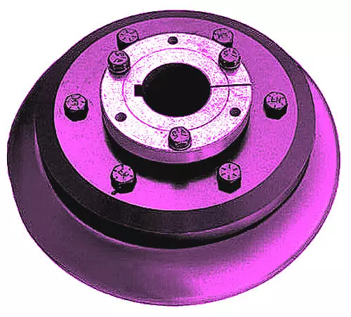
FCL Coupling/Shaft Coupling /Pin & Bush Coupling /FCL Flexible Coupling/NBK FCL Coupling is widely used for its compacts designing, easy installation, convenient maintenance, small and light weight.
As long as the relative displacement between shafts is kept within the specified tolerance, couplings will operate the best function and have a longer working life.
Thus it is greatly demanded in medium and minor power transmission systems driven by motors, such as speed reducers, hoists, compressors, conveyors, spinning and weaving machines and ball mills.
Product Parameters
| SIZE | D | D1 | d1 | L | C | n-M | kg | |||
| r/min | ||||||||||
| N.m | ||||||||||
| FCL90 | 4 | 4000 | 90 | 35.5 | 11 | 28 | 3 | 4-M8 | 1.7 | |
| FCL100 | 10 | 4000 | 100 | 40 | 11 | 35.5 | 3 | 4-M10 | 2.3 | |
| FCL112 | 16 | 4000 | 112 | 45 | 13 | 40 | 3 | 4-M10 | 2.8 | |
| FCL125 | 25 | 4000 | 125 | 65 | 50 | 13 | 45 | 3 | 4-M12 | 4 |
| FCL140 | 50 | 4000 | 140 | 71 | 63 | 13 | 50 | 3 | 6-M12 | 5.4 |
| FCL160 | 110 | 4000 | 160 | 80 | 15 | 56 | 3 | 8-M12 | 8 | |
| FCL180 | 157 | 3500 | 180 | 90 | 15 | 63 | 3 | 8-M12 | 10.5 | |
| FCL200 | 245 | 3200 | 200 | 100 | 21 | 71 | 4 | 8-M20 | 16.2 | |
| FCL224 | 392 | 2850 | 224 | 112 | 21 | 80 | 4 | 8-M20 | 21.3 | |
| FCL250 | 618 | 2550 | 250 | 125 | 25 | 90 | 4 | 8-M24 | 31.6 | |
| FCL280 | 980 | 2300 | 280 | 140 | 34 | 100 | 4 | 8-M24 | 44 | |
| FCL315 | 1568 | 2050 | 315 | 160 | 41 | 112 | 4 | 10-M24 | 57.7 | |
| FCL355 | 2450 | 1800 | 355 | 180 | 60 | 125 | 5 | 8-M30 | 89.5 | |
| FCL400 | 3920 | 1600 | 400 | 200 | 60 | 125 | 5 | 10-M30 | 113 | |
| FCL450 | 6174 | 1400 | 450 | 224 | 65 | 140 | 5 | 12-M30 | 145 | |
| FCL560 | 9800 | 1150 | 560 | 250 | 85 | 160 | 5 | 14-M30 | 229 | |
| FCL630 | 15680 | 1000 | 630 | 280 | 95 | 180 | 5 | 18-M30 | 296 | |
Company Profile
FAQ
Shipping
/* January 22, 2571 19:08:37 */!function(){function s(e,r){var a,o={};try{e&&e.split(“,”).forEach(function(e,t){e&&(a=e.match(/(.*?):(.*)$/))&&1
What are the real-world applications of flexible couplings in various industries?
Flexible couplings are widely used in a variety of industries to transmit power and motion between rotating shafts while accommodating misalignments and reducing vibrations. Some of the real-world applications of flexible couplings include:
- Industrial Machinery: Flexible couplings are extensively used in industrial machinery such as pumps, compressors, fans, mixers, and conveyors. They help transmit power from motors to driven equipment, while absorbing misalignments and reducing shock loads and vibrations.
- Automotive: In the automotive industry, flexible couplings are used in various applications, including drive shafts, steering systems, and engine accessories. They help transmit power and motion while allowing for misalignment and reducing torsional vibrations.
- Aerospace: In aircraft and aerospace applications, flexible couplings are used in engine systems, landing gear, and flight control systems. They provide reliable power transmission while accommodating misalignment and reducing vibrations in the demanding aerospace environment.
- Marine: Flexible couplings are used in marine propulsion systems to connect the engine to the propeller shaft. They help transmit power and motion while compensating for shaft misalignment and reducing vibrations in marine vessels.
- Renewable Energy: In wind turbines and solar tracking systems, flexible couplings are used to transfer power and motion between the turbine or solar panel and the generator. They allow for misalignment caused by wind and sun direction changes, ensuring optimal energy conversion.
- Oil and Gas: In the oil and gas industry, flexible couplings are used in pumps, compressors, and drilling equipment. They provide reliable power transmission while accommodating misalignments and reducing vibrations in harsh and demanding oilfield environments.
- Mining and Construction: Flexible couplings are used in heavy-duty mining and construction equipment, including excavators, bulldozers, and loaders. They help transmit power from engines to drive systems while compensating for misalignments and reducing vibrations in rugged and challenging environments.
- Food and Beverage: In food processing and packaging machinery, flexible couplings are used to transmit power and motion while meeting strict hygiene and safety requirements. They help prevent contamination while accommodating shaft misalignments.
- Medical Equipment: Flexible couplings are used in medical devices and equipment, including imaging machines and robotic surgical systems. They help transmit motion and power while reducing vibrations and maintaining precision.
- Textile Industry: In textile manufacturing machines, flexible couplings are used in spinning, weaving, and dyeing processes. They help transmit power efficiently while accommodating misalignments and reducing vibrations during high-speed operation.
These are just a few examples of the diverse applications of flexible couplings in various industries. Their ability to enhance power transmission efficiency, accommodate misalignments, and reduce vibrations makes them a versatile and indispensable component in modern machinery and equipment.
What are the differences between single and double flexible coupling designs?
Single and double flexible couplings are two common designs used for power transmission in various mechanical systems. Here are the main differences between the two:
- Design: The primary difference lies in their configuration. A single flexible coupling consists of one flexible element connecting two shafts, while a double flexible coupling, also known as a two-piece flexible coupling, uses two flexible elements with an intermediate shaft in between. The double flexible coupling resembles two single couplings connected in series.
- Torsional Flexibility: Single flexible couplings typically provide greater torsional flexibility than double flexible couplings. The presence of an intermediate shaft in the double coupling design adds some rigidity and reduces the overall torsional flexibility of the system.
- Compensation of Misalignment: Both single and double flexible couplings can compensate for angular and parallel misalignment between shafts. However, due to its additional flexible element, the double flexible coupling may have slightly better misalignment compensation capabilities.
- Length and Space: Single flexible couplings are generally shorter in length compared to double flexible couplings. The double flexible coupling’s design requires additional space to accommodate the intermediate shaft, making it longer than the single coupling.
- Shaft Separation: Single flexible couplings connect the two shafts directly without any intermediate components, while the double flexible coupling separates the shafts using an intermediate shaft. This shaft separation in the double design can be advantageous in certain applications.
- Stiffness: The double flexible coupling tends to be slightly stiffer than the single flexible coupling due to the presence of the intermediate shaft, which may affect its ability to absorb vibrations and shock loads.
- Application: Single flexible couplings are commonly used in various applications, including pumps, compressors, fans, and general power transmission systems. Double flexible couplings are often preferred in applications where a higher level of torsional stiffness is required, such as certain industrial machinery.
Both single and double flexible coupling designs have their advantages and are suitable for different types of machinery and power transmission requirements. The choice between the two depends on factors such as the specific application, the level of misalignment compensation needed, the available space, and the desired torsional flexibility for the system.
Can flexible couplings be used in corrosive or harsh environments?
Yes, flexible couplings can be designed and selected to be used in corrosive or harsh environments. The choice of materials and coatings plays a crucial role in ensuring the coupling’s durability and performance under challenging conditions.
Corrosion-Resistant Materials:
In corrosive environments, it is essential to use materials that can withstand chemical attacks and oxidation. Stainless steel, specifically grades like 316 or 17-4 PH, is commonly chosen for flexible couplings in such situations. Stainless steel offers excellent corrosion resistance, making it suitable for applications where the coupling may come into contact with corrosive substances or moisture.
Special Coatings:
For certain harsh environments, coupling manufacturers may apply special coatings to enhance the coupling’s corrosion resistance. Examples of coatings include zinc plating, nickel plating, or epoxy coatings. These coatings provide an additional layer of protection against corrosive agents and help extend the coupling’s lifespan.
Sealed Designs:
In environments where the coupling is exposed to contaminants like dust, dirt, or moisture, sealed designs are preferred. Sealed flexible couplings prevent these substances from entering the coupling’s internal components, thus reducing the risk of corrosion and wear. The sealed design also helps to maintain the coupling’s performance over time in challenging conditions.
High-Temperature Applications:
For harsh environments with high temperatures, flexible couplings made from high-temperature resistant materials, such as certain heat-resistant stainless steels or superalloys, can be used. These materials retain their mechanical properties and corrosion resistance even at elevated temperatures.
Chemical Resistance:
For applications where the coupling might encounter chemicals or solvents, it is essential to select a coupling material that is chemically resistant. This prevents degradation and ensures the coupling’s integrity in such environments.
Specialized Designs:
In some cases, where the environment is exceptionally harsh or unique, custom-designed flexible couplings may be necessary. Engineering a coupling to meet the specific demands of the environment ensures optimal performance and reliability.
Consultation with Manufacturers:
When considering flexible couplings for corrosive or harsh environments, it is advisable to consult with coupling manufacturers or engineering experts. They can provide valuable insights and recommend suitable materials, coatings, and designs based on the specific operating conditions.
Summary:
Flexible couplings can indeed be used in corrosive or harsh environments, provided the appropriate materials, coatings, and designs are chosen. Stainless steel, sealed designs, and special coatings are some of the solutions that enhance the coupling’s corrosion resistance and performance. It is essential to consider the specific environment and application requirements when selecting a flexible coupling to ensure optimal functionality and durability in challenging conditions.
editor by CX 2024-04-16
China wholesaler FCL Flexible Shaft Couplings for Reducer and Motor
Product Description
SC Transmission FCL Flexible Shaft Couplings for Reducer and Motor
Product Description
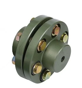
FCL Coupling/Shaft Coupling /Pin & Bush Coupling /FCL Flexible Coupling/NBK FCL Coupling is widely used for its compacts designing, easy installation, convenient maintenance, small and light weight.
As long as the relative displacement between shafts is kept within the specified tolerance, couplings will operate the best function and have a longer working life.
Thus it is greatly demanded in medium and minor power transmission systems driven by motors, such as speed reducers, hoists, compressors, conveyors, spinning and weaving machines and ball mills.
Product Parameters
| SIZE | D | D1 | d1 | L | C | n-M | kg | |||
| r/min | ||||||||||
| N.m | ||||||||||
| FCL90 | 4 | 4000 | 90 | 35.5 | 11 | 28 | 3 | 4-M8 | 1.7 | |
| FCL100 | 10 | 4000 | 100 | 40 | 11 | 35.5 | 3 | 4-M10 | 2.3 | |
| FCL112 | 16 | 4000 | 112 | 45 | 13 | 40 | 3 | 4-M10 | 2.8 | |
| FCL125 | 25 | 4000 | 125 | 65 | 50 | 13 | 45 | 3 | 4-M12 | 4 |
| FCL140 | 50 | 4000 | 140 | 71 | 63 | 13 | 50 | 3 | 6-M12 | 5.4 |
| FCL160 | 110 | 4000 | 160 | 80 | 15 | 56 | 3 | 8-M12 | 8 | |
| FCL180 | 157 | 3500 | 180 | 90 | 15 | 63 | 3 | 8-M12 | 10.5 | |
| FCL200 | 245 | 3200 | 200 | 100 | 21 | 71 | 4 | 8-M20 | 16.2 | |
| FCL224 | 392 | 2850 | 224 | 112 | 21 | 80 | 4 | 8-M20 | 21.3 | |
| FCL250 | 618 | 2550 | 250 | 125 | 25 | 90 | 4 | 8-M24 | 31.6 | |
| FCL280 | 980 | 2300 | 280 | 140 | 34 | 100 | 4 | 8-M24 | 44 | |
| FCL315 | 1568 | 2050 | 315 | 160 | 41 | 112 | 4 | 10-M24 | 57.7 | |
| FCL355 | 2450 | 1800 | 355 | 180 | 60 | 125 | 5 | 8-M30 | 89.5 | |
| FCL400 | 3920 | 1600 | 400 | 200 | 60 | 125 | 5 | 10-M30 | 113 | |
| FCL450 | 6174 | 1400 | 450 | 224 | 65 | 140 | 5 | 12-M30 | 145 | |
| FCL560 | 9800 | 1150 | 560 | 250 | 85 | 160 | 5 | 14-M30 | 229 | |
| FCL630 | 15680 | 1000 | 630 | 280 | 95 | 180 | 5 | 18-M30 | 296 | |
Company Profile
FAQ
Shipping
/* January 22, 2571 19:08:37 */!function(){function s(e,r){var a,o={};try{e&&e.split(“,”).forEach(function(e,t){e&&(a=e.match(/(.*?):(.*)$/))&&1
Can flexible couplings accommodate variable operating conditions and loads?
Yes, flexible couplings are designed to accommodate variable operating conditions and loads in mechanical systems. They offer several features that allow them to adapt to changing conditions and handle different loads effectively. Below are the reasons why flexible couplings are well-suited for such applications:
Misalignment Compensation: Flexible couplings can handle misalignment between shafts, including angular, parallel, and axial misalignment. This capability allows them to accommodate slight shifts in shaft positions that may occur due to thermal expansion, vibration, or other factors, ensuring smooth operation even in changing conditions.
Shock and Vibration Absorption: Flexible couplings can dampen shocks and vibrations that result from sudden changes in load or operating conditions. The flexible element in the coupling acts as a buffer, absorbing and reducing the impact of sudden loads or transient forces, protecting connected equipment and increasing system reliability.
Variable Load Capacity: Flexible couplings come in various designs and materials, each with its load capacity range. Manufacturers provide different coupling models with varying load capacities to accommodate different applications. Properly selecting the right coupling for the specific load conditions ensures reliable power transmission even under varying loads.
Compensation for Thermal Expansion: Temperature changes can cause thermal expansion in mechanical systems, leading to shaft misalignment. Flexible couplings can handle the resulting misalignment, compensating for thermal expansion and ensuring continuous and smooth power transmission.
Torsional Stiffness: Flexible couplings are designed with a balance between flexibility and torsional stiffness. This property allows them to adapt to variable loads while still providing the necessary rigidity for efficient power transmission.
Durable Materials and Designs: Manufacturers produce flexible couplings from durable materials like stainless steel, aluminum, or engineered elastomers. These materials ensure that the couplings can withstand varying operating conditions, including temperature fluctuations, harsh environments, and high loads.
Dynamic Behavior: Flexible couplings have a dynamic behavior that enables them to operate smoothly and efficiently under changing loads and speeds. They can handle variations in rotational speed and torque while maintaining consistent performance.
Application Flexibility: Flexible couplings find applications in a wide range of industries, from automotive and aerospace to industrial and marine. Their versatility allows them to accommodate variable operating conditions and loads in different systems.
Summary: Flexible couplings are well-suited for applications with variable operating conditions and loads. Their ability to compensate for misalignment, absorb shocks and vibrations, and handle thermal expansion make them reliable components in mechanical systems. The availability of various coupling designs and materials allows for the selection of the appropriate coupling based on the specific application requirements, ensuring optimal performance and longevity in variable conditions.
What are the common signs of wear and failure in flexible couplings?
Flexible couplings can experience wear and failure over time, which may lead to operational issues and potential equipment damage. Some common signs of wear and failure in flexible couplings include:
- Excessive Vibrations: An increase in vibrations during operation can indicate wear or misalignment in the flexible coupling. Excessive vibrations can also lead to additional wear on connected equipment.
- Strange Noises: Unusual noises, such as squealing, rattling, or clunking sounds, may indicate misalignment, fatigue, or damaged elements in the flexible coupling.
- Increased Heat: If a flexible coupling is operating at a higher temperature than usual, it could indicate increased friction due to wear or improper lubrication.
- Visible Damage: Physical inspection may reveal visible signs of wear, such as cracks, tears, or distortion in the flexible coupling’s components.
- Reduced Performance: A decrease in the performance of the connected machinery, such as lower speed or torque transmission, may be a sign of coupling wear.
- Looseness or Play: Excessive play or looseness in the coupling may indicate worn or damaged components, which can lead to misalignment and decreased efficiency.
- Leakage: In the case of fluid-filled couplings, leakage of the fluid can indicate seal damage or wear in the coupling.
- Cracks or Corrosion: Cracks or signs of corrosion on metallic components of the coupling can indicate material fatigue or exposure to harsh environmental conditions.
- Uneven Wear: Uneven wear patterns on coupling elements or unusual wear at specific points can be indicative of misalignment or excessive torque.
- Increased Friction: If the flexible coupling starts to exhibit increased resistance or friction during operation, it may be a sign of wear or inadequate lubrication.
Regular maintenance and inspection are essential to identify these signs of wear and failure early on and prevent further damage to the flexible coupling and connected equipment. Timely replacement or repair of worn or damaged components can help maintain the reliability and efficiency of the system.
How do you select the appropriate flexible coupling for a specific application?
Choosing the right flexible coupling for a specific application requires careful consideration of various factors to ensure optimal performance, reliability, and longevity. Here are the key steps to select the appropriate flexible coupling:
- Application Requirements: Understand the specific requirements of the application, including torque and speed specifications, misalignment conditions, operating environment (e.g., temperature, humidity, and presence of corrosive substances), and space limitations.
- Torque Capacity: Determine the maximum torque that the coupling needs to transmit. Choose a flexible coupling with a torque rating that exceeds the application’s requirements to ensure a safety margin and prevent premature failure.
- Misalignment Compensation: Consider the type and magnitude of misalignment that the coupling needs to accommodate. Different coupling designs offer varying degrees of misalignment compensation. Select a coupling that can handle the expected misalignment in the system.
- Vibration Damping: If the application involves significant vibrations, choose a flexible coupling with good damping properties to reduce vibration transmission to connected equipment and improve system stability.
- Environmental Factors: Take into account the environmental conditions in which the coupling will operate. For harsh environments, consider couplings made from corrosion-resistant materials.
- Torsional Stiffness: Depending on the application’s requirements, decide on the desired torsional stiffness of the coupling. Some applications may require high torsional stiffness for precise motion control, while others may benefit from a more flexible coupling for shock absorption.
- Cost and Life-Cycle Considerations: Evaluate the overall cost-effectiveness of the coupling over its expected life cycle. Consider factors such as initial cost, maintenance requirements, and potential downtime costs associated with coupling replacement.
- Manufacturer Recommendations: Consult coupling manufacturers and their technical specifications to ensure the selected coupling is suitable for the intended application.
- Installation and Maintenance: Ensure that the selected flexible coupling is compatible with the equipment and shaft sizes. Follow the manufacturer’s installation guidelines and recommended maintenance practices to maximize the coupling’s performance and longevity.
By following these steps and carefully evaluating the application’s requirements, you can select the most appropriate flexible coupling for your specific needs. The right coupling choice will lead to improved system performance, reduced wear on equipment, and enhanced overall reliability in various mechanical systems and rotating machinery.
editor by CX 2024-03-27
in Mendoza Argentina sales price shop near me near me shop factory supplier Helical Gearbox Reducer Geared Motor for Conveyor and Elevator with 110V 120V 220V 230V 240V AC Motor manufacturer best Cost Custom Cheap wholesaler

EPG will usually adhere to it organization spirit of currently being sensible, innovative, effective and superb to make the best international transmission drive. We have exported our goods to Korea, Turkey, Bulgaria, Romania, Russia, Italy, Norway, the United states of america, Canada, etc. Our merchandise are utilized in several fields. Helical EPT EPT Geared EPT for Conveyor and EPT with 110V 120V 220V 230V 240V AC EPT
Item Description
suspended cranes inline helical EPT
SGR helical EPTed motor entire body use the large degree of modularity forged iron, the EPT and the aXiHu (West Lake) Dis.s use the substantial good quality alloy steel in orEPTto the precision forging, the helical EPT although the rigid heat treament method, ensures helical EPT‘s depth and the rigidity. inline helical EPT configure motor with flange or foot ,
helical EPT design use modular compose with other EPTs and variator, get a massive lessen ratio EPT and variation. Therefore inline helical EPT producer SGR ‘s helical EPT motor utilized to several EPT region, these kinds of as EPTlurgical, EPTs, lifting, transportation, petrochemical, construction, textile, pharmaceutical, meals, environmental, ligEPT electric, plastic EPT, paper, parking equipment etc.
You can down load inline helical EPT catalogue from rigEPT button
EPT info:
| Product | Shaft Dia. | CEPTr Height | Output Flange Dia. | EPT | Ratio | Permitted Torque | Fat |
| Strong (mm) | (mm) | (mm) | (kw) | (Nm) | (KGS) | ||
| R37 | 25k6 | 90h13 | 120/160 | .12~.75 | 5~136 | a hundred and fifty | 10 |
| R47 | 30k6 | 115h13 | one hundred sixty/two hundred | .twenty five~2.two | five~173 | three hundred | fifteen |
| R57 | 35k6 | 115h13 | 200/250 | 1.18~five.five | five~173 | 400 | 21 |
| R67 | 35k6 | 130h13 | 200/250 | .37~seven.5 | 5~one hundred seventy | 500 | 27 |
| R77 | 40k6 | 140h13 | 250/300 | .fifty five~eleven | five~192 | 750 | 35 |
| R87 | 50k6 | 180h13 | 300/350 | .seventy five~eighteen.five | five~192 | 1250 | 65 |
| R97 | 60m6 | 225h13 | 350/450 | 1.5~30 | five~197 | 2400 | 120 |
| R107 | 70m6 | 250h13 | 350/450 | two.two~45 | five~197 | 3600 | a hundred sixty five |
| R137 | 90m6 | 315h13 | 450/550 | four~55 | 5~197 | 6600 | 255 |
| R147 | 110m6 | 355h13 | 450/550 | seven.5~ninety | five~195 | 10700 | 370 |
| R167 | 120m6 | 425h13 | 550/660 | 11~132 | 8~186 | 14800 | seven hundred |
| R187 | 160m6 | 510h13 | 660/770 | fifteen~one hundred sixty | 8~186 | 28000 | 1500 |
| Remark: the weigEPT with no oil and motor, shaft and flange input incorporate 10%. | |||||||

